Home
Wing Attach
History/Background
Empennage
Flap/Aileron
Fuselage
Finishing 1
Finishing 2
Finishing 3
Flight Controls
Rudder Pedals
External Step
Seat Backs
Pitot Static Line
Aft Top Skin
Skin Time Lapse
Instrument Panel
Wing Top Skin
Electric Aileron Trim
Attaching Tail
Canopy
Landing Gear
Wiring
Destinations
Sale Items

RV-6A Project Website

Instrument Panel

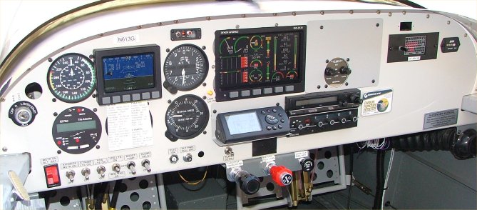
New Panel Layout with Dynon EMS-D120 - March 2008
finishedpanel.jpg

panel.jpg

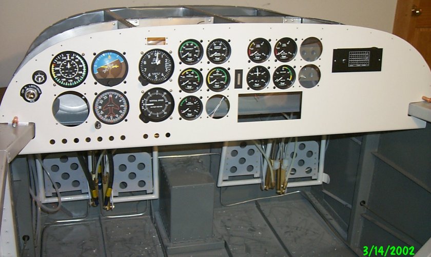
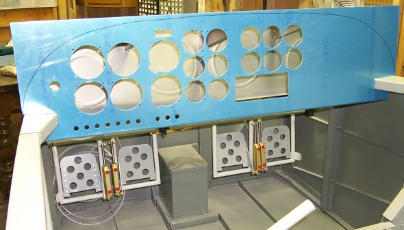
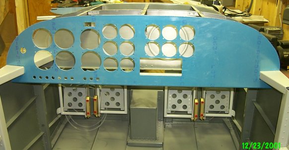
I started with Van's pre-punched instrument panel. I had it powder coated because the surface is much more durable than the paints I had been using.

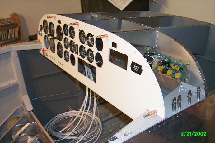
The layout worked for my planned panel and it was considerably easier starting with most of the holes drilled. I've added trim indicators, vacuum gauge, and the indicator panel for the control vision load center. I will need to add carb heat, radio (for music), intercom, and Hobbs meter.

rv6a.jpg

Van's pre-punched panel comes with the instrument holes drilled as shown. The builder cuts the notches left and right to allow the panel to fit over the canopy decks.

The cut that is made to make the panel fit under the forward top skin follows a line drawn on the back of the panel, not the front line that is shown. I used a metal yardstick laying across the firewall bulkhead and the panel behind the instrument panel. I marked spots all across the panel where the yardstick hit the back of the panel. I connected those lines and cut. From there, you file and try the panel under the forward top skin.

rv6a.jpg

Here is the panel cut to its approximate shape. An outline of aluminum right angle will be added to the back of the panel and the forward top skin will attach to that.

panel3.jpg

I finally added the platenuts to the supports. The Control Vision Load Center is seen attached to the sub panel.