Home
Wing Attach
History/Background
Empennage
Flap/Aileron
Fuselage
Finishing 1
Finishing 2
Finishing 3
Flight Controls
Rudder Pedals
External Step
Seat Backs
Pitot Static Line
Aft Top Skin
Skin Time Lapse
Instrument Panel
Wing Top Skin
Electric Aileron Trim
Attaching Tail
Canopy
Landing Gear
Wiring
Destinations
Sale Items

RV-6A Project Website

Electric Aileron Trim

rv6a.jpg

Electric Aileron Trim is a 1" x 6" tab added to the trailing edge of the left aileron. The tab is driven by a servo mounted inside the aileron and controlled from the pilot's control stick.

rv6a.jpg

On the quick build, you start by cutting into a perfectly good aileron. A patch panel will cover the hole when I am done. I will also remove the edge before I'm done, but left it there to strengthen the bottom lip of the existing skin while I worked.

rv6a.jpg

The servo will mount to the bottom of this piece with its arm pointing away from the camera. The vertical face (far side) will mount to the spar reinforcement plate that you make. The servo mounts so that it is sticking half-way through the spar in a rectangular hole.

rv6a.jpg

This photo shows the reinforcement plate with its cutout. This plate goes over the spar where a large cutout and spar lightening holes leave a strange opening through the spar. I used blind rivets to fasten this plate.

The servo can be extracted from within the aileron with the two screws shown.

wingskin3.jpg

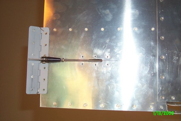
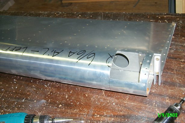
Find the location for the slot by measuring the distance from the top side edge to the center of the shaft, then transfer that distance to the bottom side using the bottom edge as a reference. Make a small slot to start and enlarge it as needed for shaft movement.

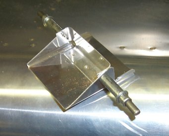
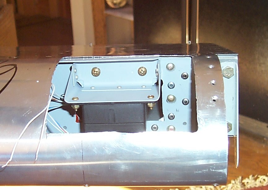
The control that is mounted to the hinge is clearly shown on the drawings.

rv6a.jpg

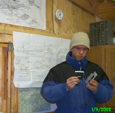
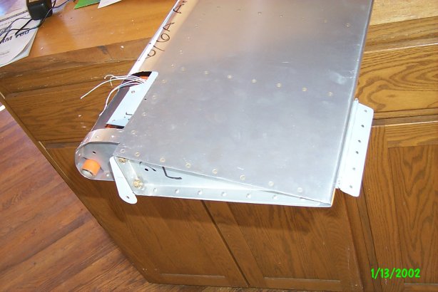
When you don't want to wait for the kerosene heater to warm the shop, bundle up and grab some cold aluminum. I thought this was "sweat equity"?!